
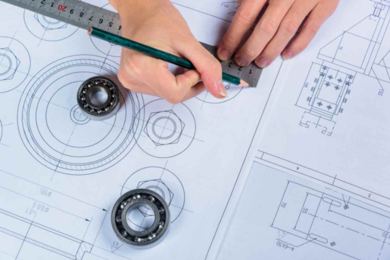
Concept and Design
a. Define the product's purpose and specifications, including voltage and current requirements.
b. Determine the topology and configuration of the power electronics circuit (e.g., inverters, converters, motor drives, etc.).
c. Create a schematic and layout design.
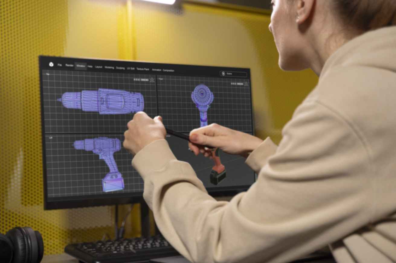
Simulation and Analysis
a. Simulate the circuit design using software tools (e.g., SPICE, PLECS) to ensure it meets performance and efficiency goals.
b. Perform thermal and electromagnetic interference (EMI) analysis to address heat dissipation and EMI concerns.
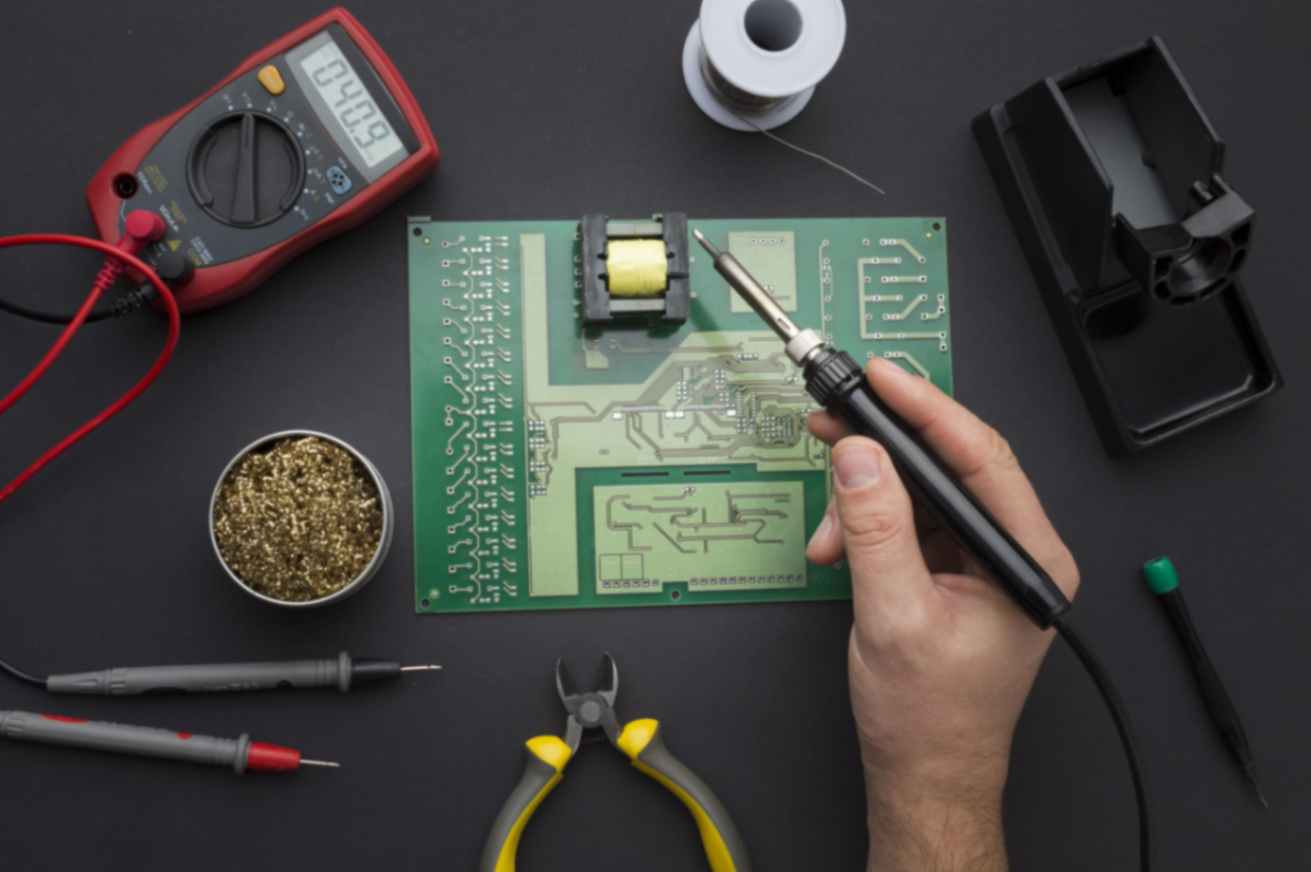
Prototype Development
a. Build a prototype of the power electronic circuit.
b. Test the prototype for functionality and performance.
c. Make necessary adjustments and improvements based on the test results.
PCB Layout and Manufacturing
a. Create a printed circuit board (PCB) layout based on the schematic design.
b. Send the PCB design to a manufacturer for production.

Component Procurement
a. Source and purchase all required components and materials.
b. Ensure components meet necessary quality standards.
Assembly and Manufacturing
a. Assemble the power electronic product, including soldering components onto the PCB.
b. Perform quality control checks during the assembly process to detect and rectify any defects.

Firmware and Software Development
a. Develop control algorithms and software for the power electronic product.
b. Test and debug the software to ensure proper operation and safety.

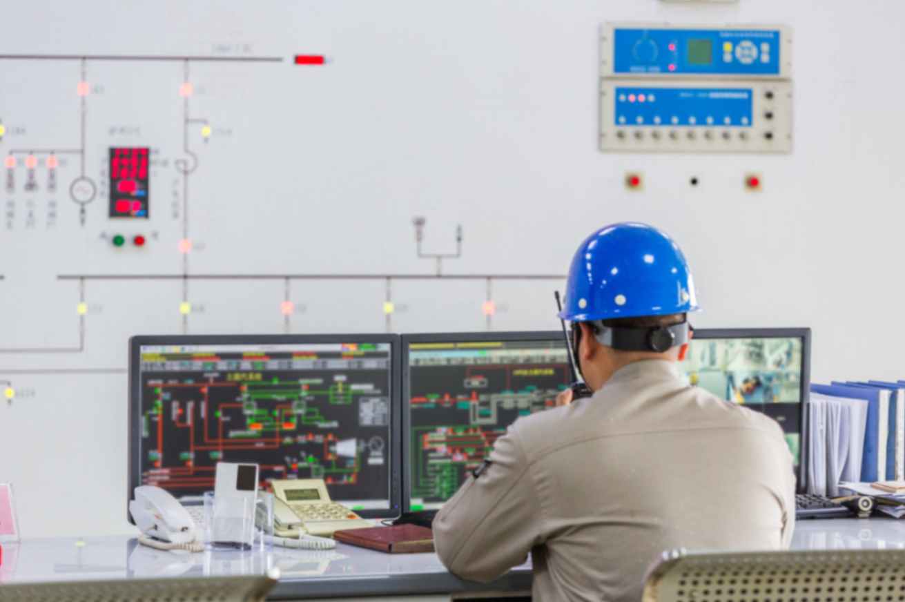
Testing and Validation
a. Conduct extensive testing, including functional tests, safety tests, and performance tests.
b. Ensure compliance with relevant industry standards and regulations (e.g., UL, CE, IEEE).
c. Perform environmental and reliability testing to assess the product's long-term performance and durability.

Certification and Compliance
a. Obtain necessary certifications and approvals from regulatory bodies if applicable.
b. Ensure the product meets safety and environmental standards.